TLR Control Electronics
From essential modules to fully configurable control systems
Reliability and Safety for Every Pressure Washer
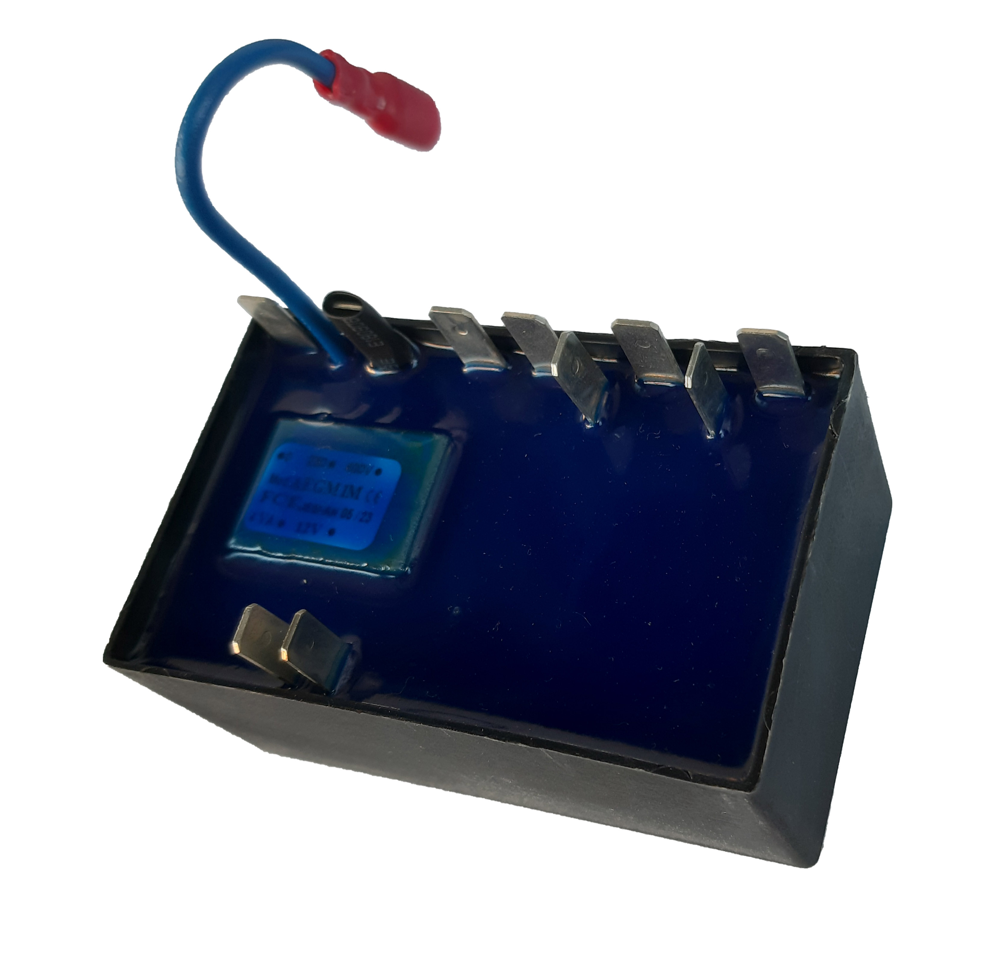
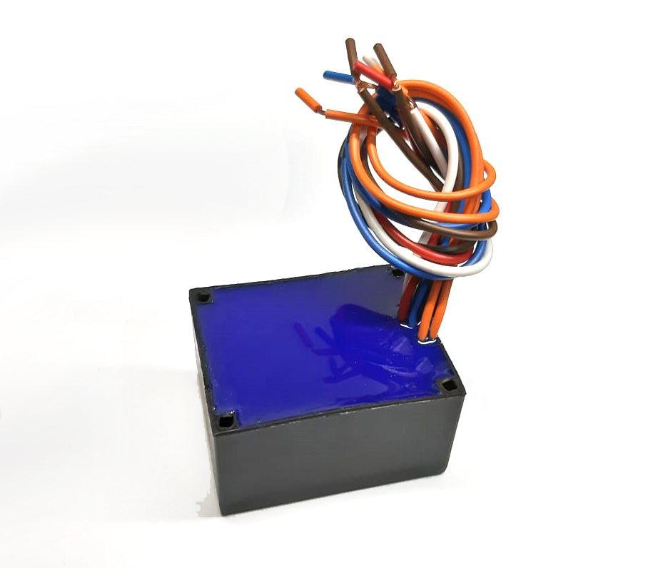
The TLR product line is engineered to ensure safe, stable and reliable operation of pressure washers, even under harsh working conditions. From simple delay modules to advanced, fully configurable control units, each board is designed to withstand moisture, vibration, thermal stress and heavy-duty cycles, guaranteeing long-term durability and maximum protection of the machine.
Comparison Table⭐ PREMIUM
🔥
❄️
⚡230V
⚡400V
TLR FULL
230Vac: 5,5kW-7,5Hp
400Vac: 7,5kW-10Hp
Fully Customizable
❄️
⚡230V
⚡400V
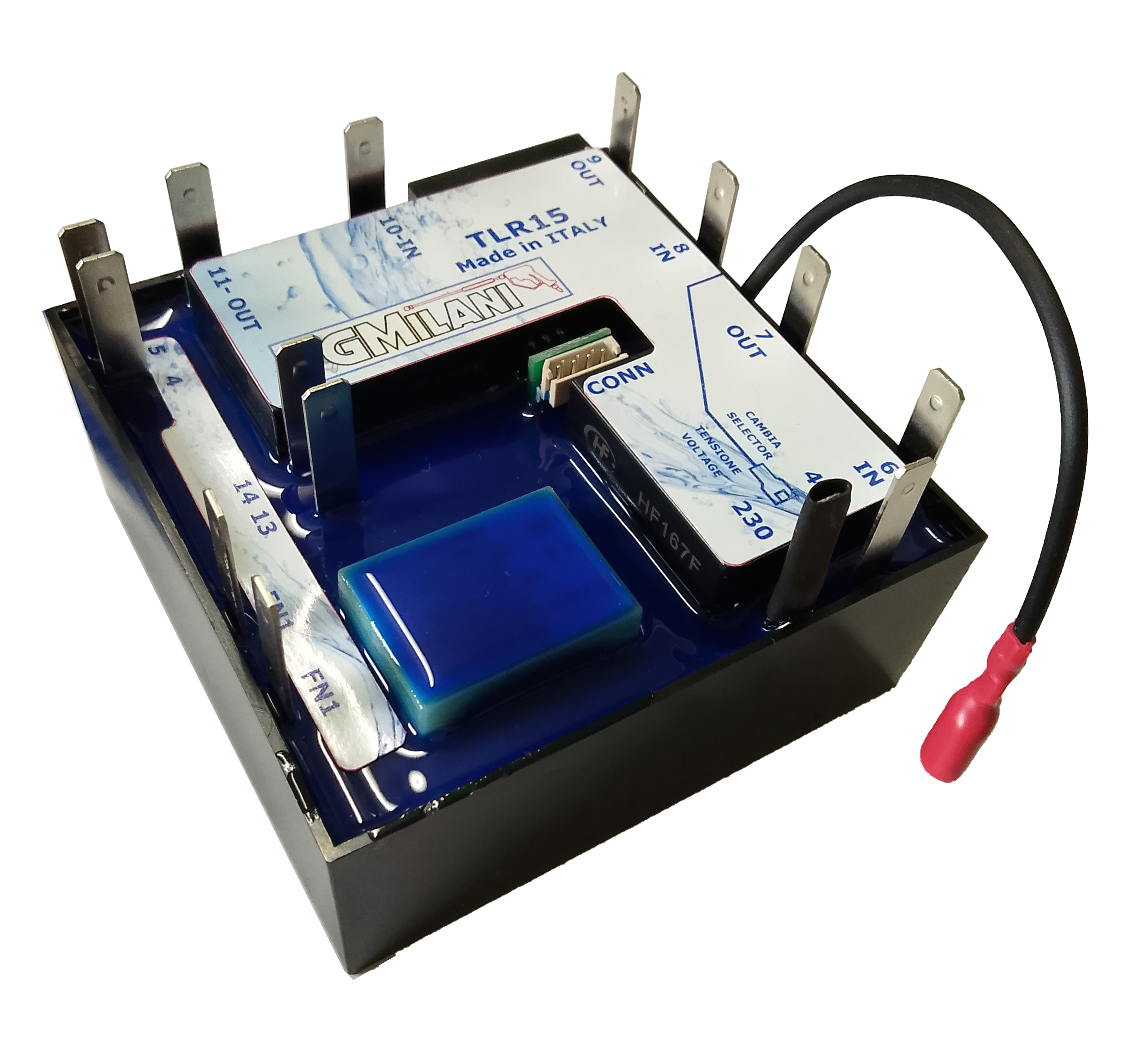
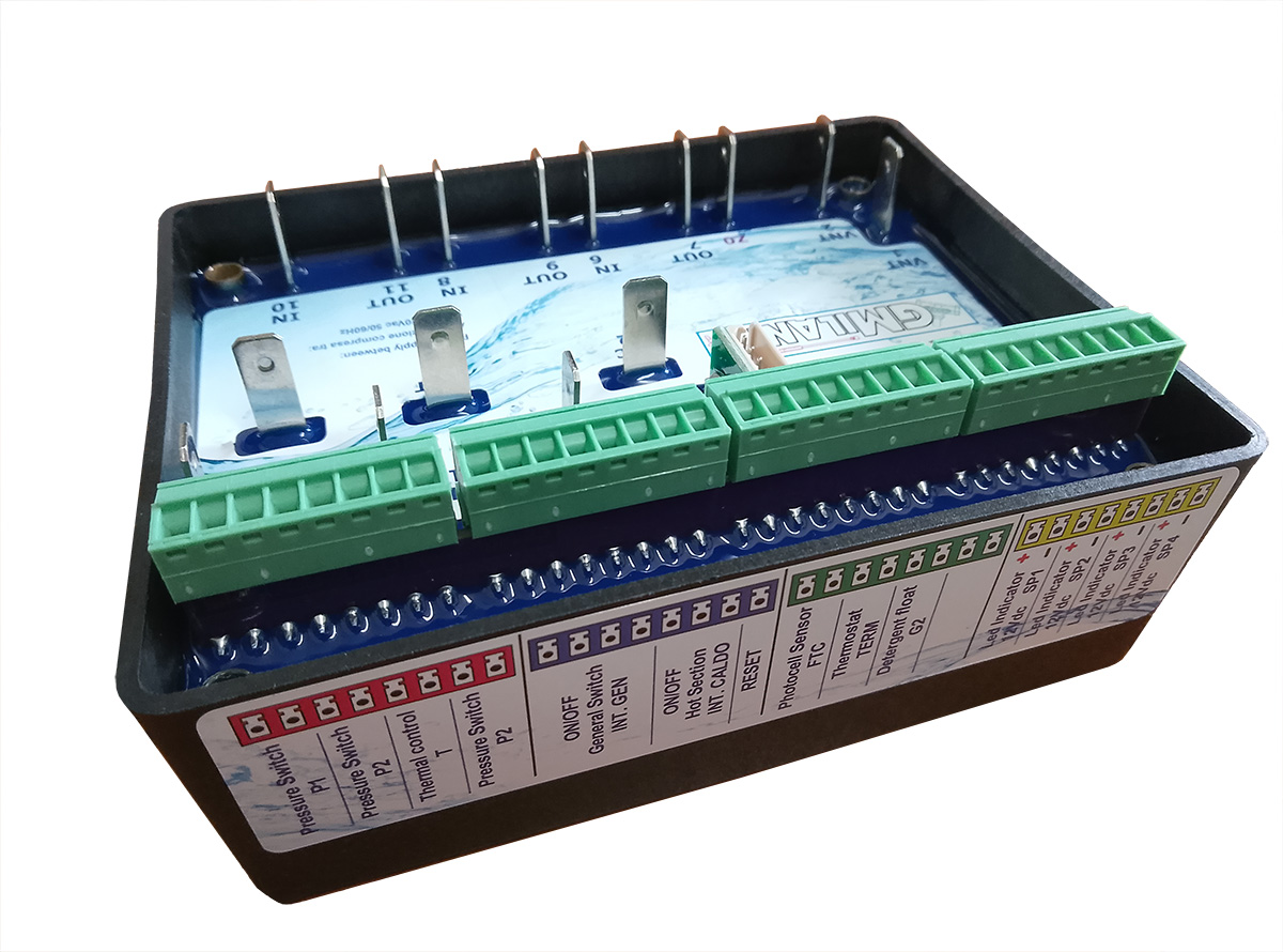
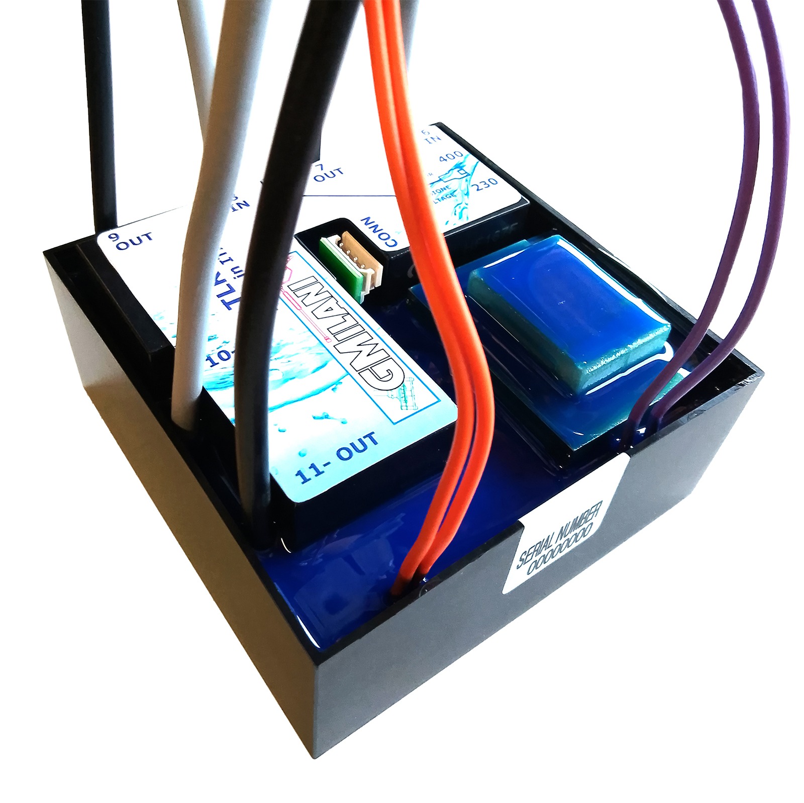
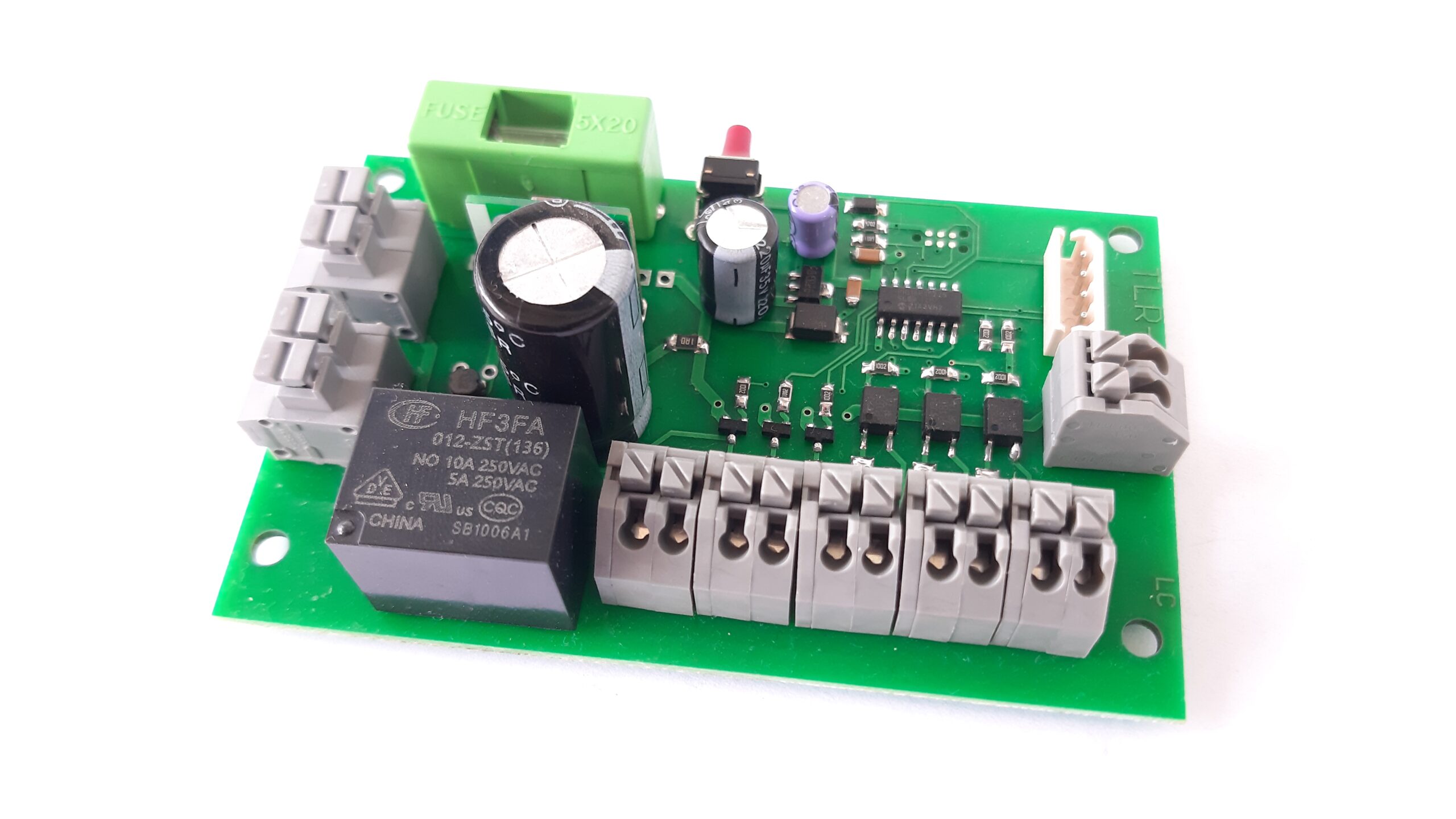
TLR 15
230Vac: 8kW-10,8Hp
400Vac: 15kW-20Hp
PC-Configurable - Max. 15kW
❄️
⚡230V
⚡400V
TLR 20
230Vac: 8kW-10,8Hp
400Vac: 20kW-27Hp
PC-Configurable - Max 20kW
🧠 ADVANCED
🔥
❄️
⚡230V
⚡400V
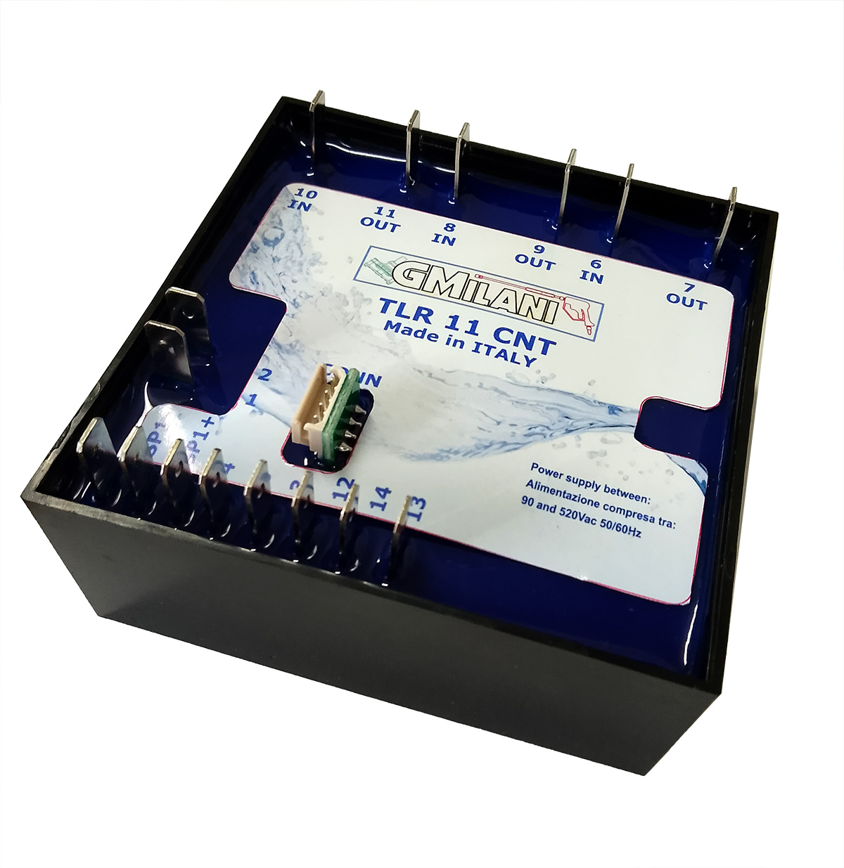
TLR 11 CNT
230Vac: 5,5kW-7,5Hp
400Vac: 7,5kW-10Hp
MCU based - PC-Configurable
❄️
⚡230V
⚡400V
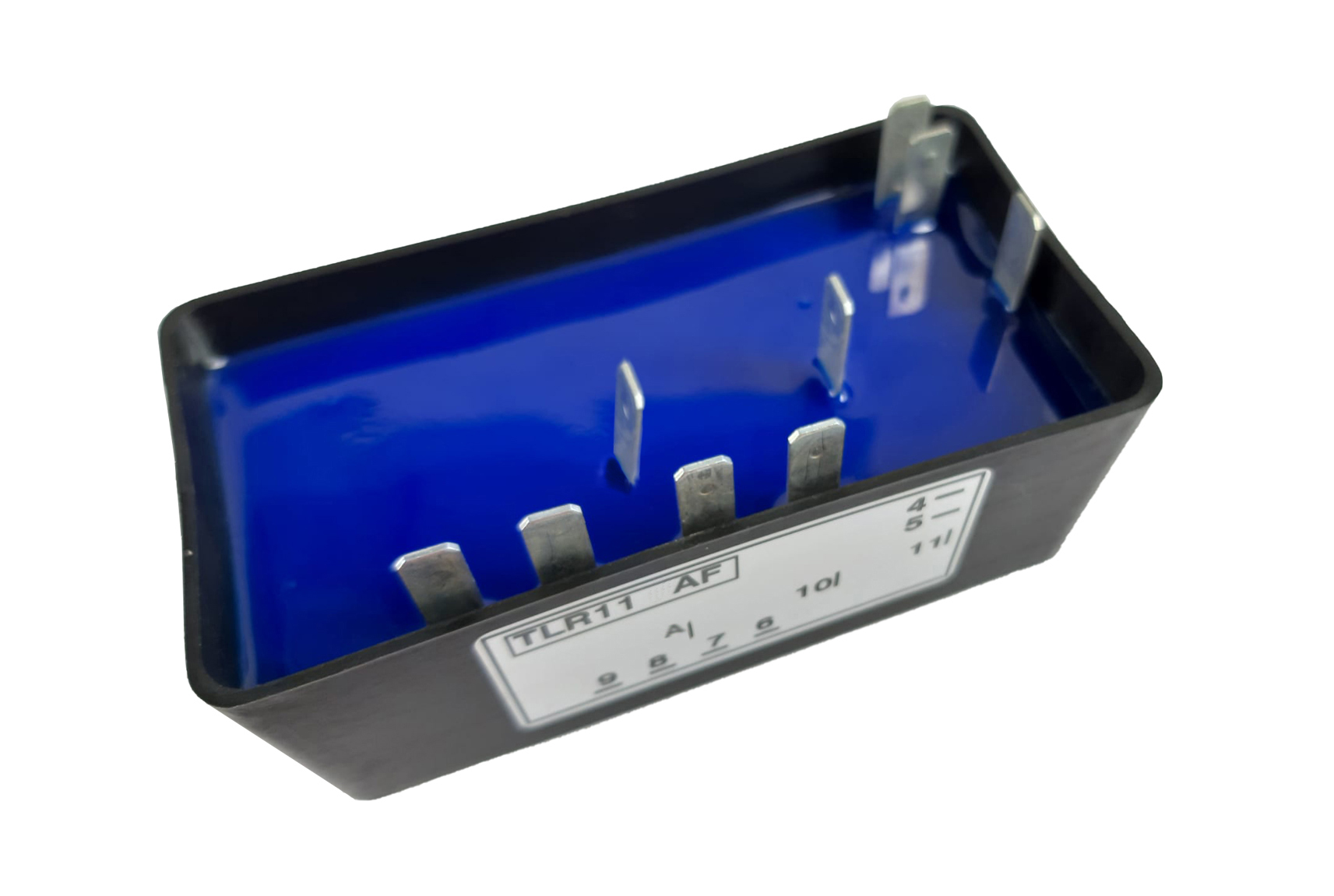
TLR 11 AF
230Vac: 5,5kW-7,5Hp
400Vac: 7,5kW-10Hp
Automatic supply‑voltage recognition (90–520 Vac)
🔥
❄️
⚡230V
⚡400V
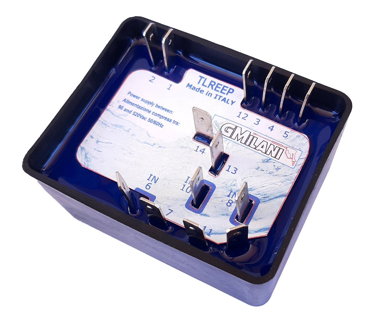
TLR 4 EEP
230Vac: 3kW-4Hp
400Vac: 4kW-5Hp
Automatic supply‑voltage recognition (90–520 Vac)
🔥
❄️
⚡230V
⚡400V
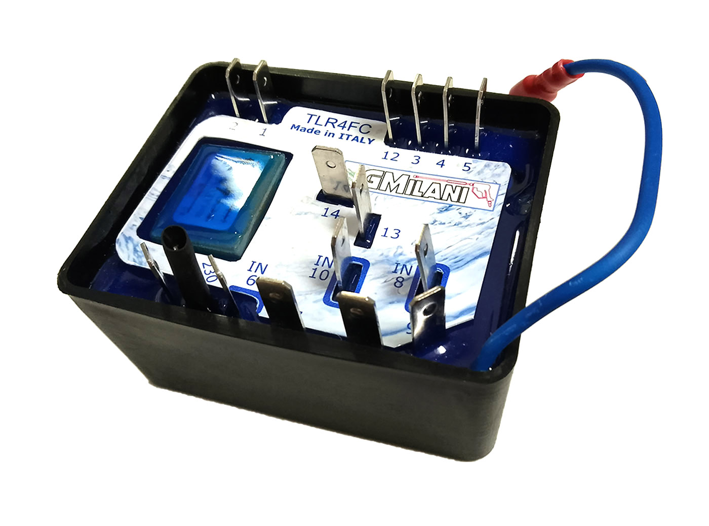
TLR 4 FTC
230Vac: 3kW-4Hp
400Vac: 4kW-5Hp
Configurable MCU based control with diagnostics
⚙️ STANDARD
🔥
❄️
⚡230V
⚡400V
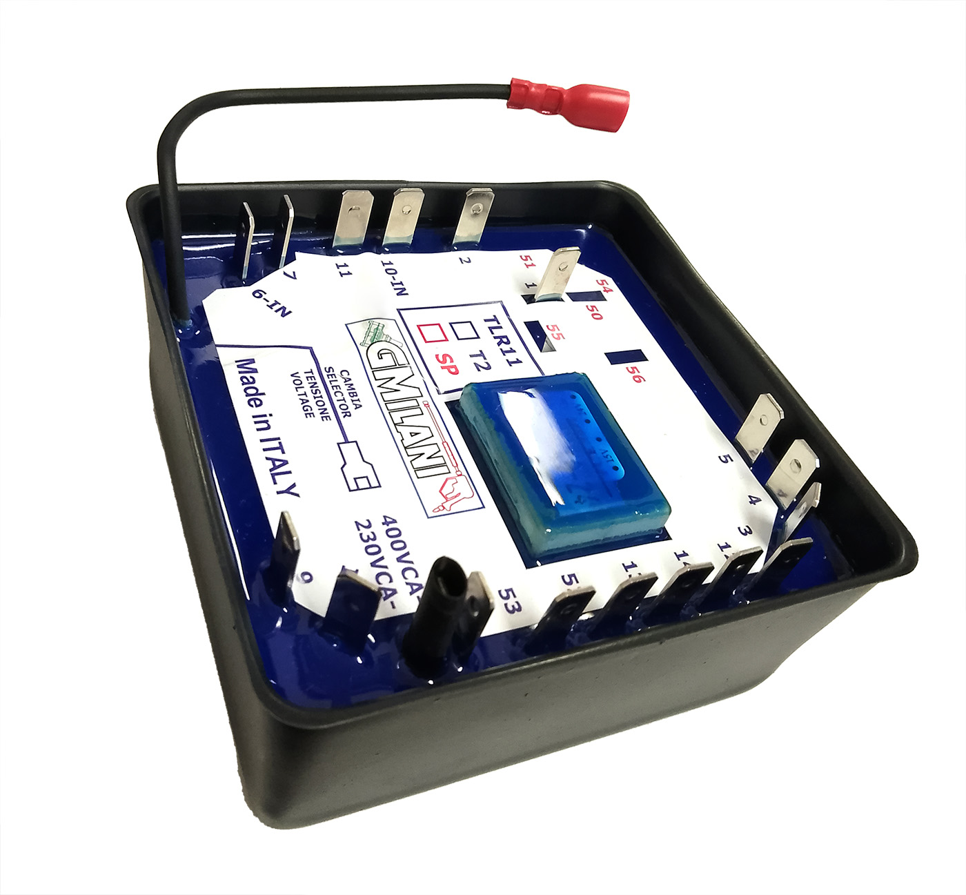
TLR 11
230Vac: 5,5kW-7,5Hp
400Vac: 7,5kW-10Hp
24Vac - 150mA Aux. Out
🔥
❄️
⚡230V
⚡400V
TLR 4 FC
230Vac: 3kW-4Hp
400Vac: 4kW-5Hp
Diesel solenoid safety shutdown on water‑loss
❄️
⚡230V
⚡400V
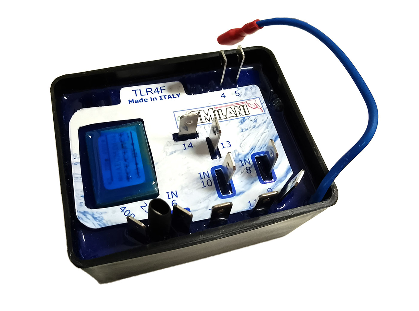
TLR 4 F
230Vac: 3kW-4Hp
400Vac: 4kW-5Hp
13‑second TOTALSTOP for cold‑water systems
📦 BASIC
❄️
⚡230V
⚡400V
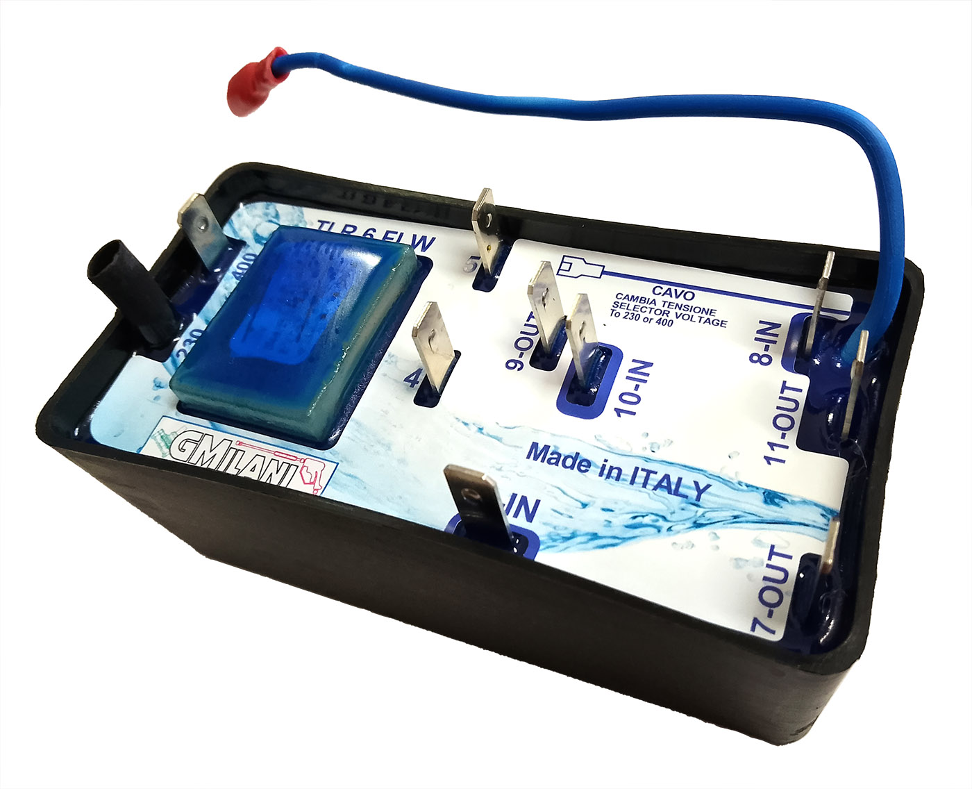
TLR 6 FLW
230Vac: 4kW-5,4Hp
400Vac: 5,5kW-7,5Hp
Pump activation only on pressure‑switch closure
❄️
⚡230V
⚡400V